

Choosing a Location
Before installing a Rain Can select a suitable location.
Consider the following when choosing the Rain Can location:
- The Rain Can must not receive any coverage from sprinklers.
- The Rain Can must have a clear view of the open sky.
- Avoid mounting the Rain Can where its opening may be blocked by walls, structures or foliage.
- Avoid installing near trees that may eventually obstruct the Rain Can’s operation.
- The base of the Rain Can must be open to allow drainage. Standoffs are provided with the Rain Can for mounting on flat surfaces.
- Consider a location that is easily accessible for future maintenance. Avoid locations where access requires an extension ladder.
- Consider providing protection from birds and/or other critters. Bird-B-Gone Strips (Figure 2) designed to fit the standard 4” (10.16 cm) Rain Can are available

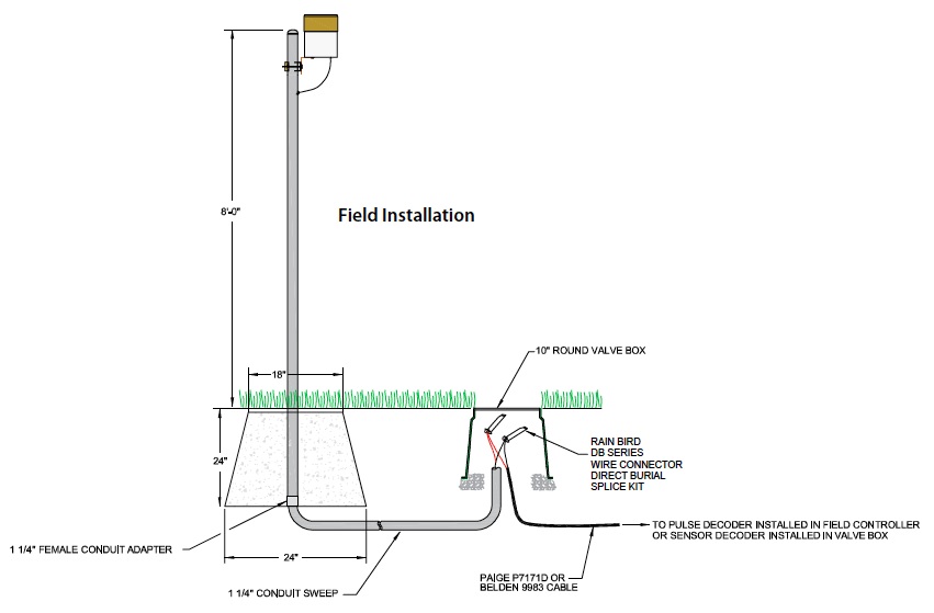
Installation
A typical Rain Can installation is shown in the drawing show here. A clear and unobstructed mounting location is necessary to obtain accurate rainfall readings. The Rain Can must be mounted level for proper operation of the tipping mechanism and accurate recording of rainfall. The mount for the Rain Can should be sturdy enough to allow very little to no movement in windy conditions, vibrations from movement due to wind will reduce accuracy. Excessive movement of the Rain Can may cause incorrect readings to be generated from the tipping assembly.
Reasonable protection must be provided for the communication wire to prevent damage from string trimmers or other maintenance equipment. Electrical conduit is typically sufficient for this purpose. Adequate protection for any splice points must be considered as well, DBRY100 or an equivalent.

Communication Wire
A 60’ (18.29 m) length of communication wire is provided with Rain Can . All splices in the communication wire should be encapsulated in DBRY100 Wire Connectors or an equivalent direct bury splice pack. Any wire exposed above the surface should be routed through electrical conduit for added protection.
Maintenance
Over time, the opening of the Rain Can may become clogged by leaves, twigs, bird droppings, etc. and should be checked and maintained regularly to ensure accurate and reliable operation. To clean the Rain Can, first loosen the set screw on the collar of the funnel assembly and remove the funnel assembly that holds the screen (Figure 4).
Debris may now be more easily removed from the Rain Can assembly, at this point the funnel and screen may be cleaned or replaced if needed, this includes the tipping bucket, as any accumulation of debris can adversely affect calibration, (Figure 8 shows the tipping assembly). Removal of the Rain Can body may help with cleaning and maintenance, this can be done by removing the two screws on the bottom of the body (Figure 5).
Before replacing the funnel assembly, confirm that the drain holes on the bottom of the Rain Can are open and unobstructed allowing for drainage. Gently move the tipping bucket from one side to the other once or twice to make sure it is moving freely. Replace the funnel assembly and tighten the set screw on the collar. Confirm that the opening to the Rain Can is level when the funnel assembly is fully seated. If the opening is not level, adjust the body of the Rain Can to the level position.


Troubleshooting
If measurable rainfall occurs, but is not recorded by the central control software, the following steps may be used to help isolate and correct the cause of the issue:
- At the Rain Can, loosen the set screw on the collar of the funnel assembly and remove the funnel assembly (Figure 7 and 8).
- Confirm the screen and funnel are clean and unobstructed
- Confirm the tipping mechanism moves freely


- Gently tip the bucket on the tipping mechanism back and forth at least 5 times, pausing for 1-2 seconds between each tip. Count the number of total tips.
- Return to the central computer and verify if tips were recorded
- If no tips were recorded continue to Step 3
- Disconnect the Rain Can communication wire from the field control equipment. Touch the input wires of the field control equipment device together briefly, to generate pulses that will be read by the central. Do this at least 5 times, pausing for 1-2 seconds between each contact. It is not necessary to count the number of times the wires are connected; you simply check for a non-zero count.
-
- Return to the central computer and verify if tips were recorded
- If no tips were recorded continue to Step 4
- If tips were recorded in the central computer, it is reasonable to presume the issue is in the Rain Can or the communication wire between the field control equipment and the Rain Can.
- Check the communication wire and all splices between the field control equipment and the Rain Can.
- Check the spacing between the magnet on the tipping mechanism and the reed switch on the Rain Can. The magnet on the tipping bucket should be 1-2 mm from the reed switch. If this distance is greater the tipping mechanism may need to be adjusted closer to the reed switch.
- To adjust the distance between the magnet and the reed switch you need a hex key. The adjustment point is shown in Figure 9 below.
- Check the connection of the monitoring device to the field control equipment and verify that it is operating correctly. This may require a troubleshooting guide for the specific field control equipment in use.
- Confirm RainWatch™ settings are properly configured in the central control software
- Decoder System
- Confirm the SD-210 is configured for the correct Box, Wire Group and the address is correct.
- Confirm RainWatch™ settings are properly configured in the central control software
- Satellite System – Hard Wired
- At the Pulse Decoder, confirm it is configured for the correct Channel number. In the central control software confirm the correct Box and Wire Group are selected for the MIM the Pulse Decoder is connected to.
- Confirm RainWatch™ settings are properly configured in the central control software.
- Satellite System – LINK
- Confirm the Satellite controller is set to the correct Channel number and note the sensor sub-channel (a or b) the Rain Can is connected to. In the central control software confirm the correct Box and Wire Group are selected for the MIM-LINK the Satellite is connected to. Verify the proper sub-channel (a or b) has been selected in the Rain Can configuration.
- Confirm RainWatch™ settings are properly configured in the central control software.
- Decoder System
